So-called PWM or Pulse Modulation Witdh is a technique often used to control a load, for example, is the DC motor speed control, PWM techniques are often used.
Usually to make a simple PWM (for practice or introduction PWM) of the hobbyist to use some of the circuit made of Op-Amp, which consists of Schmitt Trigger circuit, integrator and comparator.
Schmitt Trigger function that produces a square wave will be converted by the integrator sawtooth wave or commonly also called Ramp, and Ramp compared with a reference voltage that can be changed much voltage. So the result is a PWM output.

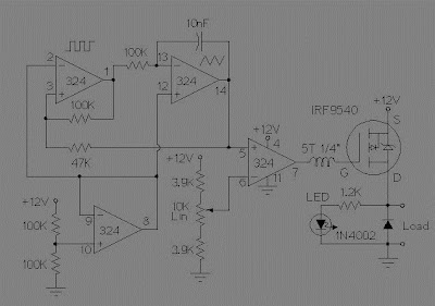
Skema Rangkaian High Side PWM Motor/Light Controller
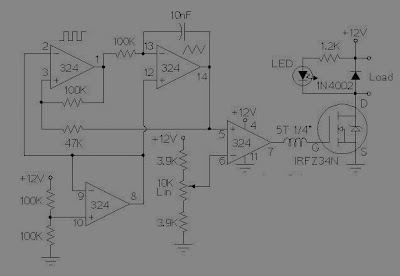
These two schematics are variations on another PWM circuit. The diagrams are for 12V operation only and there are high side (common ground) and low side (common +12V) versions. The low side version of the circuit uses an N Channel FET, the high side version of the circuit uses a P Channel FET. N Channel devices tend to handle more current than P Channel devices, they are also less expensive. The high side version of the circuit is useful when one side of the load has to be grounded.
This circuit can switch a fairly high amount of current, an IRFZ34N MOSFET can handle over 35 Amps if connected to a proper heat sink. Higher power FETs, such as the IRFZ48N or IRF1010Z can be substituted if even larger currents are required. It is also possible to connect multiple FETs in parallel for even more current capacity. Always use thermally conductive grease between the FET and the heat sink, and remember that the heat sink is electrically live.
Inductive loads (motors) may require special care since they can generate large voltage spikes that can damage the MOSFET. Replacing the 1N4002 with a fast recovery diode may help absorb the reverse voltage kick when driving an inductive load such as a motor. If you use these circuits for experiments with electric vehicles, be sure to install a circuit breaker in series with the battery, the circuit breaker should be easy to reach by the driver. This is especially important due to the fact that when MOSFETs fail, they often short out, leaving the motor on at full speed.
Terima kasih telah membaca artikel tentang Pengatur Kecepatan Motor Menggunakan PWM di blog Kumpulan Skema Elektronika jika anda ingin menyebar luaskan artikel ini di mohon untuk mencantumkan link sebagai Sumbernya, dan bila artikel ini bermanfaat silakan bookmark halaman ini diwebbroswer anda, dengan cara menekan Ctrl + D pada tombol keyboard anda.

