 |
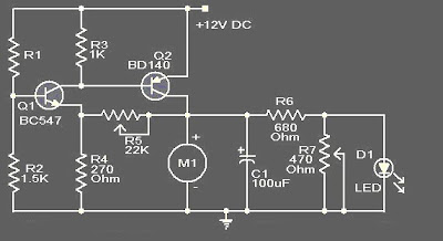
| Skema rangkaian fan control suhu otomatis |
Note:
- R1 can be a 15K @ 20�C ,N.T.C thermistor.
- M1: DC Fan 12V,700mA fan motor.
- Capacitor C1 must be rated 25V.
- The circuit can be powered from a 12V PP3 battery or 12V DC power supply.
About thermistor
The standard leaded thermistors are calibrated and tested at 20 �C to a tolerance of � 5 % or � 10 %; however, tighter tolerance, point matched thermistors are readily available as are special point match temperatures to fit your application. Since these thermistors have only one controlled point of reference (the point match temperature), the resistance at other
temperatures is given by the �Resistance vs. Temperature Conversion Tables� for the appropriate material curve. The resistance value at any temperature is the ratio factor times the resistance at 25 �C. The resistance vs. temperature conversion tables can
be found at: www.vishay.com/doc?33004 and www.vishay.com/doc?33011.
Terima kasih telah membaca artikel tentang Rangkaian Fan Control Suhu Otomatis di blog Kumpulan Skema Elektronika jika anda ingin menyebar luaskan artikel ini di mohon untuk mencantumkan link sebagai Sumbernya, dan bila artikel ini bermanfaat silakan bookmark halaman ini diwebbroswer anda, dengan cara menekan Ctrl + D pada tombol keyboard anda.